( You may think this outdated, however,
your new DSS will change your mind ! )
This page was from http://www.butler.edu/jcfa/t-com/uhfguide.html, but since that one disappeared I'm keeping this copy on my server.
The purpose of this Guide is to provide information for improving UHF television reception in the home. The Federal Communications Commission originally allocated twelve channels for television broadcasting. These channels, numbers 2 through 13, are in the "very high frequency" or VHF band. (Originally Channel 1 was also included, but was soon reassigned to other purposes.)
The tremendous growth in television broadcasting following World War II made it obvious that 12 channels were not enough. So in 1952, the FCC allocated 70 additional channels above the VHF television band and called them "ultra high frequency" or UHF band. The channels are 14 through 83. UHF signals, however, due to the physics of radio frequency transmission, are inherently less efficient in the conversion of radio waves to the electrical signals used by the television receiver, and are subject to more losses from some environmental conditions then VHF. Good UHF reception, therefore, requires more attention to antenna installation and set tuning than does VHF reception. On the other hand some VHF channels are subject to certain types of interference to which UHF channels are generally immune.
Simply stated, clear UHF reception requires more attention to antenna installation and set tuning than does VHF reception. While the broadcasting industry is working to improve the technical elements of UHF reception, there is much that can be done, at reasonable cost, with present available equipment-and that's what this publication wants to reveal.
Perfect reception for television signals can't be guaranteed simply because there are too many variables involved. However, by following the recommendations in this Guide, the chances for clear reception will be greatly improved.
Improving UHF reception can be a do-it-yourself job. Even if the work is given to a professional, the information in this guide will provide a better understanding of what is needed and what can be expected.
If UHF reception in general is bad, how it's bad can help determine the problem. "Snow" is visual noise caused by a weak signal. poor antenna system, the set itself, or a combination of these. "Ghosts" or multiple images are caused by a signal arriving from two or more directions simultaneously reflected off buildings, trees and mountains. A good antenna system often solves these reception problems. An outdoor antenna is better than an indoor antenna. An indoor antenna is better than no antenna at all. If an outdoor antenna is needed for VHF, you'll almost certainly need an outdoor antenna for UHF. But if good VHF reception can be obtained with and indoor antenna, a loop or other UHF antenna on the set may also work.
Indoor antennas
All indoor antennas can be adversely affected by the walls of a house,
inadequate height, and by movement of people in the room-as may be noticed
with VHF "rabbit ears."
Loop or single bow tie UHF antennas are usually not satisfactory. They
are difficult to adjust for maximum signal pick up or for elimination of
ghosts. Be sure their lugs are secure to the UHF antenna terminals on the
back of the set.
The indoor combination VHF/UHF antenna has a multi-position switch to get
the best picture. As a rule, this type of antenna is not good for UHF.
The rod antenna, or "monopole," is a VHF/UHF antenna found on some portable
sets, Normally UHF reception is poor, but can be enhanced when the rod is
telescoped to its smaller size.

The best indoor antenna
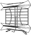
If an indoor UHF antenna must be used, the two-bay bow tie with a reflector screen (pictured) is the best choice. But, keep in mind, outdoor antennas are always better than indoor antennas. Make sure the antenna wires are connected to the UHF terminals on the back of the TV set.
There are many different kinds of outdoor antennas available in a wide price range. The kind selected is determined primarily by the geographic location of the receiver.
 [ Recommended UHF antennas: four-way bow tie (pictured), 7-10 dB gain,
for
metropolitan areas with strong signal. Eight-way bow tie (similar),
10-13db gain for suburban
areas with medium signal. ]
Television signals are strongest when the station transmitting tower and the home receiving antenna are in line-of-sight. If the line-of-sight is blocked or weakened by mountains, buildings or trees, the signal, likewise will be weakened or lost. The signal will also grow weaker as it travels farther.
"Gain" is the measure of an antenna's sensitivity-- and its ability to pick up signals. It is measured in decibels (dB). The farther away from the station tower, the more gain the antenna should have. Gain can also vary from channel to channel. For example, an antenna's advertised gain rating may be at Channel 20, but the gain may be much less at Channel 69. Make sure the dealer guarantees that the antenna purchased is for channels in your area.
Where buildings or other obstructions cause "ghosts," an antenna with good directivity is recommended. Directivity is the ability to receive only those signals at which an antenna is pointed. Highly directive antennas have narrow receiving angles (measured to degrees) and high "front to back ratios." To insure the best reception aim the antenna carefully.
If a good VHF antenna installation is already on hand, it will probably be less expensive to add a good quality UHF antenna on the same mounting mast, The separate UHF antenna also will permit pointing to VHF and UHF antennas independently.
 [ Yagi (pictured) with corner reflector, 13-16dB gain, for deep fringe
areas with low signal. ]
If all television signals are coming from the same direction, both VHF and UHF reception can be improved. Choose an antenna according to the distance to the most distant UHF station for which reception is desired by installing an all-channel combination antenna. Combining both antennas in a single mechanical structure imposes design problems which make the selection of a well-engineered antenna very important.
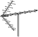
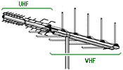
 [ Outdoor combination antenna: log periodic with yagi. (pictured) ]
There are several good combination VHF/UHF antennas available. One of the best types combine a "log periodic" VHF antenna with a "yagi" UHF antenna on a single horizontal boom. If the UHF stations to be received are located in different directions from the house (more than 30 degrees apart):
A good lead-in line installation delivers the signal from antenna to set with relatively little loss of strength. Choose a quality grade of either one. Flat ribbon twin lead, shielded twin lead and solid core coaxial cable don't work well for UHF. Lead-in lines deteriorate over time. Lead-in lines over five years old (or less depending on environmental conditions) should be replaced with new cables.
Twin lead vs. coaxial cable
Coaxial Cable (75 ohm line)
A good installation can be made using either type of line. Get professional help if you have special problems like local interference or very weak signals. Few sets still have 300 ohm antenna connectors, a matching transformer to connect coaxial cable to the set will be needed.
With separate VHF and UHF antennas, separate lead-in lines are used to connect them to their respective terminals on the television set. Most combination VHF/UHF antennas have a connection for a single lead-in line, and in most locations a single high quality lead-in line will deliver good VHF and UHF signals. However, a single line cannot be connected to both the VHF and UHF 300 ohm terminals Instead, a good VHF/UHF "splitter"-rated 300 ohms for twin lead or 75 ohms for coaxial is required. Connect the lead-in line to one end, and the two pairs of wires at the other end to the appropriate set terminals.
Splitters (also called "mixers") can also reduce signal strength. So in a weak signal area, use separate lead-ins or add a booster amplifier to the antenna. If a booster amplifier is added, it should be in the line before any splitters, and as close to the antenna as practical.
More than one television set (or FM radio) may be connected to one antenna by using a multiple set "coupler." Most couplers weaken signals. If signals are weak a coupler and an amplifier may be needed, which substantially increased the cost. It may be cheaper to erect a second antenna
All televisions sets, particularly older ones, add some noise or "snow" to weak UHF signals. A booster (or preamplifier) may reduce the snow, but first be sure a good antenna installation is in place. Keep in mind, outdoor booster antenna are more efficient than indoor models mounted at the set.
Reguardless of initial quality, antennas and lead-in lines gradually deteriorate with age. Pollutants and salt ocean air are particularly destructive. Check the complete installation and hose the antenna with water yearly.
Cable systems rarely carry a UHF station on its own UHF channel. UHF stations are usually transmitted either on an unused VHF channel or on one of the special cable channels available through a set-top converter furnished to the subscriber. The cable company will provide a listing of channels to which the UHF channels have been converted.
Take care to fine tune the channel on which the UHF station is supposed to appear, or some of the service paid for will be missed.
Occasionally a converted UHF signal will show interference from a strong adjacent channel. If a neighbor of yours has the same problem with his television set, ask the cable company to correct the problem.